Work on topology optimized floor diaphragms for maximum in-plane stiffness was presented at Nordic Steel 2019 in Copenhagen, Denmark and at the 12th Canadian Conference on Earthquake Engineering in Quebec City, Canada.
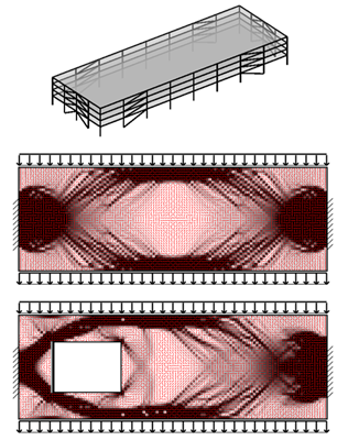
In the reported SDII research the diaphragms are loaded with inertia forces from the floor mass in the form of a uniform line load on the edges and the diaphragm’s lateral supports are at the locations of the vertical lateral force resisting systems (e.g. the braced frames), indicated in the 4 story SDII archetype building in the top figure. The two figures show the optimized layout of bare steel diaphragms with and without a cutout for maximum in-plane stiffness when type of steel diaphragm can be varied (e.g. number of fasteners, plate thickness, etc.) this is indicated with shapes of grey (black is high stiffness, white is low stiffness) and the red lines defines the orientation of the corrugated steel sheets. The optimized layouts indicate the necessity of chords on either side of the diaphragm with stiffness orientation along the edge, however, traditional collectors are not shown in the optimized layouts. Instead, there is indication of an area with high strength and stiffness near the lateral supports. Furthermore, indication of transfer beams is shown between the chords and the area near the lateral supports. Work is ongoing to bring real-world constraints into the models and develop the method as a tool for improved design of diaphragms.
This work was led by SDII Ph.D. student Astrid Winther Fischer.